Introduction
Once again I am playing around with PIC microcontrollers. Now I finished a complete demo that does this:
- drive a 4-wire fan, in my case a Noctua NF-S12A using PWM
- read the fan’s tachometer output to determine its speed
- show the PWM duty cycle and fan speed on a 16×2 LCD
The demo application starts with a duty cycle of 0, where the fan doesn’t rotate and increases the duty cycle by 5% every 5 seconds, until it reaches 95%. Then it decreases the duty cycle by 5% every 5 seconds until it reaches 0. It keeps repeating this sequence forever.
At the same time it counts the pulses coming in from the fan’s tachometer output and displays the calculated speed every second.
The circuit
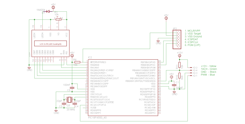
The circuit on my breadboard is made after this schematic (click to make it bigger):
The circuit to drive the fan and to read the tachometer is really simple. The microcontroller runs at 5 Volt and can directly drive the PWM input from a CCP output. The signal from the tachometer needs to be pulled up to 12V, after which simple resistor divider suffices to get that signal at the required TTL levels.
The firmware
The application is written in MPLAB X and uses Microchip’s xc8 compiler. The LCD module is borrowed and adapted from the “PC Case USB LCD” project by Simon Inns. The source is heavily commented so should be quite easy to understand.
The demo
You can see that the fan starts spinning when the system is powered up, but that it doesn’t move at duty cycles of 0 and 5%. It does start spinning at 10%.
The source
I sincerely hope that this helps someone.


